Sunday, 21 February 2016

Well Windlass

Well Windlass: From learning the meaning of the word to building it

When we were asked to make windlasses on Friday, February 5th, I didn't even know what the word meant until I saw pictures. Making an unfamiliar machine made the brainstorming processes a little more challenging than that of the bottle opener. We had to use more imagination than prior experience with the machine. But this also left us with a lot of room for creativity and exploration.

Limitations, requirements, and tips to keep in mind:

The requirements and limitations we kept in mind throughout the design and building process were:
  • Don't exceed a total of 500 cm2 acetal sheet;
  • Use up to 50 cm long acetal rod (thickness = 6.37 mm);
  • Use up to 120 cm long string;
  • Make sure the windlass can stand over a 12 cm gap between two tables: "the well";
  • Build the crank such that it is not right above the well;
  • Make sure the final structure doesn't wobble, bend or break as it lifts 1 litter of water in under 45 seconds.
  • The windlass should be able to lift the water bottle at least 10 cm above the tables' top surface. 
General guidelines we outlined before brainstorming designs:

  • Triangles and arches are better supporting structures than rectangles. 
  • The farther apart the weight is suspended from the supports connecting it to the two tables, the more our beam bends. So keep the side of the windlass across the width of the well as close as possible to 12 cm without it falling through. 
  • That said, we need a stable base and, if possible, a good grip on the table.
  • To lift the water in as small time as possible, wrap the string on a wider frame that lifts more string with one rotation. Here, we figured wrapping the string around the circumference of the acetal rod would lift the bottle extremely slowly. 

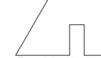
Figure 1: If the rod on the left (a) is half as wide as the rod on the right (b), the same length of string can be wrapped around (a) twice as many times as (b).


Brainstorming possible designs:

My partner, Jiaming, and I started drew some possible designs on paper. We briefly entertained the idea of using a pulley system to minimize the effort needed to lift the weight. However, given we would only be lifting 1 kg  and that we have a limited length of string to use, we went with a more traditional windlass with two bases standing on either side of the well, and a center rotating with a string to lift
the water.
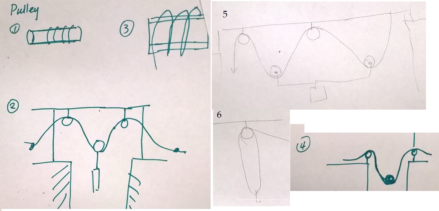
Figure 2: Very briefly considered pulley systems 


Figure 3: General outline of chosen windlass type and its components

Once we agreed on the general structure of the windlass, we focused on individual components like the base and stand, the cross-beam, the rotating center that wraps the string, the handle, and the different joints connecting these individual components.

Vertical supports and bases:
We designed triangular supports for support but varied their specific dimensions and bases to create several designs.


First, we concentrated on the base. We brainstormed some designs that would "clamp" the support with the table, and others with flat feet to prevent the vertical structure from tilting to any side. 


Figure 4: Types of bases brainstormed and their respective drawbacks


After trying a cardboard model of the "clamp" we designed and seeing that the support is too thin to hold 1 kg of load, we changed our design to look like the following triangular supports with small triangular bases.


Figure 5: Left: Triangular base that clicks with the bottom of the vertical support (center); Right: A close-up picture of the tight fit that connects the base with the vertical support

Later, we further modified our base to run across the well and connect the two supports. That way, the bottom is less likely to wobble or collapse inwards was we lift the weight.
Figure 6: Base across the well that clicks to both vertical supports

Our vertical support also went from being a triangular slab to a frame with a vertical at the center and three sides (each 2 cm wide) of an equilateral triangle. This saved us material while keeping the structure sturdy. 

Figure 7: Modified design of vertical support to conserve material


Rotating Center/Windlass and rotating axis:

Since stacking rods or building boxes to make the rotating center thicker would consume too much material, we decided to arrange four rods separated by a rigid circle to form a quasi cylindrical shape.

Figure 8: (Circular) rigid frames for cylindrical rotating center

We originally considered cutting out parts of the circle except for the rectangular lines that connect the rods with the center of the circle. However, this would have applied too much force on thin pieces of rod with the risk of breaking. So we chose stability over conservation of material. Instead we made the circles' radii smaller.

For our rotating axis, we have considered the cylindrical rod, a rectangular cutout of delrin sheet, and piano wire that would loosely attach the rotating piece with the support.

We abandoned the idea of using piano wire because it is too weak to carry 1 N of weight. Also, piano wire could only be used as an attachment, not as a functional part of the design.

We made a model that uses the cylindrical rod and realized that the rod slips from the circular hole that connects it to the circles carrying the weight of the water. While it could easily turn the circles and wrap the string without mass attached, the friction is not strong enough to lift the mass. 


Figure 9: Model of well windlass with a cylindrical rod as an axis. Note: This picture doesn't show the four rods that pass through the circles to support the string as described above.

But, if our rotating axis had a rectangular cross-section, it wouldn't slip out of a rectangular hole as we rotate it. The question, then, was "Which rod is stronger: the cylindrical rectangular one?"

When we suspended 1 kg of mass from each beam as shown in the figure below, the rectangular beam proved to be stronger (it bent less than the cylindrical one).

Figure 10: Left: Cylindrical Delrin rod bends more than Right: Rectangular Delrin rod when 1 kg of water is suspended from each

The rectangular beam is a better option both for its greater strength and because it allows rotation without sliding. Accordingly, we adjusted the center holes on the circles we designed to rotate in the middle.

However, this meant the rod wouldn't rotate very smoothly in its junction with the two vertical supports on either side. If we make the rods rectangular, the rod wouldn't rotate at all. But if we make the holes circular the rotation would be very bumpy and uneven.

To solve this, we designed bushings of 2 cm outer diameter and a rectangular hole at the center to fit the rectangular rod. This way, the bushings would rotate with the rod but slide smoothly along the circular hole in the vertical supports that loosely fit them.


Figure 11: Top left: cross section of cylindrical rod that would pass through openings in vertical stands; Bottom left: Circular opening in vertical stand to allow rotation; Top right: Bushing with rectangular opening and circular exterior to fit rectangular rod and rotate smoothly in the stands; Bottom right: Model of opening in vertical stands that would fit the circular bushing

In our final iteration, we used two of these bushings to allow smoother rotation even as the axis slides sideways slightly. We also fit two rectangular bushings slightly bigger than these on either side of the joints to prevent them from sliding too much.


Extra support:

While we were relatively confident with the ability of our structure to support 1kg of mass, we wanted to be safe and take additional measures to make sure it wouldn't deform when lifting up the weight. For this, we came up with a range of ideas:
i) Build additional triangles that would stand on the cross -beams and support the rotating axis while allowing it to rotate.
ii) Build a cross-beam that would lock the two supports from the top and with it two "hangers" that would suspend part of the mass of the rotating axis from the top cross-beam.
In addition, build two rods that connect the sides of the vertical supports at about 11 cm above the table surface. This proved to be challenging to build and attach properly. It was also not very essential given we had three cross-beams already.
iii) Replace the (rectangular) top cross-beam with an arch and have a simpler and more aesthetically appealing structure.


Figure 12: Different designs we tried for extra support labeled according to their respective descriptions above

We saw that the arch works better in terms of conserving material as well as creating a strong enough but simple structure.


Handle:
This was one of the easier parts to design. We made two rectangular pieces, one connected to the rotatable axis and the second rectangle which sticks out for us to hold as we turn the windlass.

Since we wanted a permanent connection between the two pieces to perform as one, we used thermal press to connect them.


Final Product and Performance:
Our final well windlass incorporated the best of all the parts we designed. It uses well under the limit of Delrine we were allowed to use. It wobbles slightly when lifting water due to the low friction with the table. However, when held with hand from the same side as the rotating handle, it is reasonably stable. We were able to lift the 1 litter water in under 10 seconds several times using our final product.

Areas of Parts in Final Iteration
Part (amount)
Area (cm2)
Triangular vertical supports (2)
235
Circles above well (2)
22
Bottom cross-beams (2)
64
Arch
20
Handle
25
Rectangular rotating axis
14
Bushings
33
Total
413


Note: The above areas are those of Delrin pieces cut out of 3/16’’ sheets.

We also used 28 cm of our Delrin rod and the entire 120 cm string we were allowed to utilize.

Figure 13: Final working iteration of windlass: Top left: Top view; Top right: Front view for user accessing the handle; Bottom: Side view
Figure 14: Evolution of our well windlass from earliest to latest (left to right)

What would I change/improve:

I would replace the handle with the cylindrical delrin rod for a more comfortable grip.
I would also attach the support and base with the table (with a clamp, for example) for better stability. This could also be solved by adding more mass to the supports.
And if I was to mass manufacture this windlass, I would use more 3 dimensional parts to replace the small parts put together like a puzzle, for ease of manufacturing. For example, I would use a 3-D printer to make one whole piece of cylinder rather than four rods arranged to resemble one or a one-piece handle rather than two pieces put together.


Thank you for your time.

Best,
Meba


Archives: Among the many many photos we took to document this process:


Monday, 15 February 2016

Mechanism: Cams and Followers

On Friday February 12, we discussed different mechanisms of changing certain types of input forces and movements into outputs of different forces and movements. 

We discussed:
* gears and gear trains used in clocks, for example;
* belt and chain drives (as in bikes);
* cams and followers
* and linkages

I am especially interested in cams and followers because they operate on a very simple logic, yet can be used in a variety of ways to transfer rotational motion to linear or another form.  

Cams and followers (as the name suggests) consist of two main parts: i) cams drive the motion (by rotating about a fixed axis, for example) while brushing against followers; ii) followers are pushed to varying degrees based on the dimension and motion of cams.

A very simple example of cams and followers can be set up using a book (or any material that can be made into an incline plane) and a pencil. 
1) Hold the pencil vertically such that it can only move up or down if force is applied to it.
2) Make an incline out of the book such that it touches the pencil's tip. 
3) Now, move the book back and forth and note that the pencil moves either up or down. 

The pencil's height increases or decreases based on the height of the point it touches on the book/incline. This is shown in Figure 1 below. 

Figure 1: Cam and Follower Experiment with Pencil and Book
Source: https://www.cs.cmu.edu/~rapidproto/mechanisms/chpt6.html#HDR95

By constraining the follower's motion to suit our desired type of movement, we can use cams and followers with amazing flexibility. We can vary the shape of either or both the cam and follower, play with their dimensions, and the motion of the cam. A few examples of the different ways one can utilize cams and followers are:

Figure 2: Grooves and curvy edges used in cams and followers
Source: https://www.cs.cmu.edu/~rapidproto/mechanisms/chpt6.html#HDR95

 Notice in the above examples that the cams are rotating while the followers move up and down or back and forth perpendicular to the plane of rotation of the cams.
Figure 3: "Imperfect" circle cams and see-saw followers
 Source: http://educypedia.karadimov.info/library/rockeranim.gif

In Figure 3, the side of the follower touching the cam moves up and down and the mass on the other end of the see-saw follows the up and down motion. We can use an arrangement like this to hammer or constantly hit something vertically with the up and down motion of the other end of the follower.

According to Carnegie Mellon University's "Introduction to Mechanisms" notes, cams and followers are used in machines like "printing presses, shoe machinery, textile machinery, gear-cutting machines." They allow control over the type of motion and its timing.

There are several other uses and models of cams and followers. I find it fascinating that the simple concept that an object moves due to contact force combined with a little bit of creativity allows as to engineer a variety of machines.


Thank you for your time!

Best,
Meba


Monday, 8 February 2016

Fastening and Attaching


On Tuesday (2/2/2016), we visited three different stations to learn different ways of fastening and attaching Delrin parts together. The different stations we visitied were:

Station A: Drill press, arbor press, piano wire fastening
Station B: Thermal press
Station C: Calipers, bushing measurements and tolerances, peg and slot measurements and tolerances

Station A:
My partners from the bottle opener project, Amy and Marissa, and I visited Station A first.

Drill Press and piano wire: Drill presses allow you to make holes of a certain size to fit (loose or tight depending on your preference) a piano wire in your delrin. For example, say you wanted to connect three pieces of delrin, and want one to be fixed while the other two rotate together. You can drill the holes such that the two rotating ones fit tightly around the piano wire and the fixed one fits loosely to allow for the rotation of the others.

Using the drill press, we learned a few safety tips like:

  • keep your hair tied at all times (such that it doesn't pass your chins, in Larry's own words)
  • Fix the Derlin piece aligned to the drill. Make sure it is tightly clamped to the stand so that it doesn't rotate with the drill. 
  • And keep your fingers away from the drill until it has stopped rotating completely.

Arbor Press:
We use an arbor press to hold the piano wire aligned to the hole we made with the drill press and apply force on it for it to fit inside and connect our pieces.

Benefits and draw backs:
It is easy to accidentally drill holes that don't align or melt the Derlin from the heat of the drill, but if used with care and precision, this method works well for both tight and loose fit attachments that may or may not allow motion and can be taken apart if needed.


Station B: 
Next we visited the thermal press station where we melted two parts of Derlin together to attach them permanently. If the connection is meant to last forever, this is the best method out of the three to use. However, if one wants to rearrange the attachment later, the thermal press may not be the best option.


Safety tips around the thermal press machine:
You keep your fingers away from the tip of the heater while and after it is operating until you cool it down for 30 seconds by turning on the air supply.


The figure above shows the thermal press with its warning and the venting system with a pedal to step on (the fun part!).


Station C:
Here we used calipers to measure the dimensions of bushings, pegs and slots. These also allow tight (but not permanent) or loose attachments for pieces of Delrin. Due to uncertainties in measurement and the slight imprecision in the laser cutter, it is good to try small parts of Delrin and see how they fit before producing the life-size model. The laser cutter burns away parts and may burn slightly more than the intended. Also its intensity decreases with depth. So it cuts more of the top layer than the bottom (at an angle). Depending on which side you measure from, the width may be different.

We measured the diameter of a Delrin rod and the inside diameters of several bushings (loose, snug and tight fits).

Here I was measuring the diameter of the Delrin rod in millimeters. 

 Table 1: Measured diameters of bushings and Delrin rod

Item measured
Diameter (mm)
Sample 1
Sample two
Tight fit bushings
6.35
6.33
Snug fit bushings
6.46
6.49
Loose fit bushings
6.65
6.64
Delrin rod
6.33

 Notice that the measurements within each type of fit are different. This could be because how hard I pressed the caliper isn't perfectly controlled or simply because the cuts aren't perfect fits. Trying parts to see if they fit is safer than fully relying on measurements.

We then measured the slots already labeled with dimensions to compare intended sizes to the final measurements.


Table 2: Labeled size vs measured size of slots produced by a laser cutter
Size written (in)
Samples
Size  measured (in)
0.135

Sample 1
0.1445
Sample 2
0.1435
Sample 3
0.1425
0.125

Sample 1
0.1345
Sample 2
0.1345
Sample 3
0.1335
0.115
Sample 1
0.1250
Sample 2
0.1175
Sample 3
0.1175
Notice that there are a range of values measured for slots labeled as the same size. But what all the measured sizes have in common is that they are all larger than the written values. This is because the laser cutter burns material slightly thicker than the line we make for it to follow. So we need to account for this when making slots for any type of fit.

We measured the pegs to fit in these slots and found:
Table 3: Pegs dimensions
Dimension (in)
Peg #1
Peg #2
Length
0.4930
0.4845
Width
0.1330
 0.1394
Depth
0.1710

We then measured unlabeled blocks for the depth and width of slots and pegs and found:
Table 4: Slots and pegs (not previously labeled)
Dimension (mm)
Slots
Pegs
# 1
#2
# 1
#2
Length
9.94
5.13
9.82
5.07
Width
5.13
4.76
5.18
4.76
Depth
5.02
5.07
4.95
5.10

 Note: The dimensions the thickness of the Delrin was equal to the width of the pegs, which I labeled as 3/16 in = 4.76 mm.
The connection was a snug fit.


From this station, I have learned that measurements are largely subject to uncertainties and that one needs to account for discrepancies and try the connections before producing entire models. 


Thank you for your time.

Best,
Meba


Sunday, 7 February 2016

Bottle Opener

We are "engineering" bottle openers?

Our first project in Engineering 160 this semester was to make a bottle opener. And as a naive newbie to engineering, I suspected no challenge would come out of making such a simple tool.

I have come to respect bottle openers (or at least their engineers) more after brainstorming for, designing (multiple times), making prototypes of and testing bottle openers for over a week.

Bottle opener as a cantilever:

On the first day, we discussed the formulas for the deflection of a cantilever and modeled the tip of the bottle cap on which the opener applies force, as well as the opener itself as cantilevers.

We used the following relations to get a general sense of how to minimize the deflection of the opener while keeping it long enough to apply enough force that can open the bottle cap.

where delta = deflection (displacement of the tip);
F = force applied on cantilever;
E = young's modulus (a constant value of 2.6 GPa for Acetal and  180 GPa for stainless steel);
L = length of cantilever from fixed end to the tip
and I = moment of inertia which is obtained from the formula,
 => 

Image 1: Cantilever deflection
Displaying WP_20160207_10_03_19_Pro.jpg


Let's get sketching!

During class time on the first day of the assignment, we sketched a few possible designs. What all our designs have in common is a part that goes under the cap to apply an upward force (to uproot it) and a part that would hold down the cap from the top to fix it in place.


Image 2: Rough sketches of possible designs 

Image 3: Candidate that stood out

The bottle opener design shown in Image 3 stood out as the "cantilever" that is the least likely to bend as it is short (small L) and wide (large B). And we know from the deflection formula that  and .

After a brief consideration of a rectangular piece to go under the bottle cap, we figured a curved tip would be less likely to get chipped. 


Foam core model:

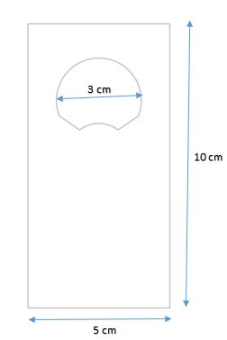
We went on to make a prototype of this design out of foam core.  We measured the diameter of the top of a bottle cap (~2.7cm) using a caliper and made a circular opening just as big in our "opener." We cut out the inside of the opener, the part that would directly contact the cap as shown in Image 4. Then, we carved out the body of the opener (shown in Image 5) such that its maximum length x base measured 10 cm x 5 cm. 


Image 4: Bottle opener part measured to fit over the bottle cap

Image 5: Top left: Cork with measured diameter (victim); Top right: Knife (trusty assistant); Bottom left: Carved out bottle opener; Bottom right: Circles making up the opening of the opener outlined


Uh-Oh! We may have a bit of a problem.

We tried to fit the carved out model with the nice curve and applied some pressure (pretending to open the bottle) and realized that the thin sides of the circular hole bend very easily. These sides are on the horizontal line connecting the intersections of the two circles marked in Image 5 above. Although foam core is much weaker than Acetal, this still shows that thin sides are more likely to break under pressure.

So we designed the opener such that two diagonals between the two circles would provide more support as in Image 6 below. We also decided to model the frame of the opener as a rectangle to prioritize functionality over aesthetics.

Another problem we noticed: The part of the opener that passes the diameter of the cap is actually narrower than the diameter of the opening. So we made the diameter of the circle 3 cm to give some room for the cap to fit.


Image 6: Bottle opener model slightly modified for better strength and fit


 On to SolidWorks:

Now that we were happier with our model, we sketched it on solid works as shown in Figure 7 below:

Image 7: SolidWorks sketch of bottle opener Version #1

We converted the SolidWorks parts document to a dxf document for the laser cutter. 


Laser Cutter:

Then came the exciting part of using the laser cutter to carve this design out of acetal! With Xi Xi's help, we positioned the acetal under the laser cutter, adjusted the height, and cut the acetal into the right shape with the flame of the laser.


Image 8: Laser cutter at work

The laser cutter literally burns parts of the acetal corresponding to the lines in the sketch. The opener looked like this as planned:


Image 9: Laser-cut acetal bottle opener (First version)


Opener to the test:

Filed the curvy tip such that it fits under a tight bottle cap (Image 10), and tried opening a tightly sealed bottle. It worked for 3 out of 4 people we tried.


Image 10: Filing down the curvy tip of our bottle opener


Image 11: Bottle Opener #1 works!

While we were excited it worked for the most part, we noted that the pointy edges make it less comfortable to hold. We also observed we may need more space at the top of the opener for two fingers of the user to rest comfortably and hold the bottle and the opener together as a fixed pivot point.


Second iteration (or third, since a new friend joined us):  

We designed our second iteration such that its edges would be curvier and its shape more comfortable for the user. The SolidWork sketch looked like this:

Image 12: SolidWork sketch of bottle opener mode - a more comfortable grip

But our next iteration got more interesting when Marissa, with her own first version for a bottle opener, joined our group. Now the task was not only touching up our original design for a more comfortable grip but also integrating the two very different designs into one.

This is what Marissa's design looked like:

Image 13: Marissa's original bottle opener design


So we decided to make a double sided opener, our different designs at each end. The second bottle opener need to have a tighter fit on the bottle cap to minimize the effort one needs to open the bottle.

As we worked to combine the designs and because we are still learning to use SolidWorks, we created an accidental curve at one edge that resembled a bird's beak.

First reaction: Oh no! What did we do?!
A few seconds later: Hmm, this actually looks like a bird now. Let's keep it!

So we measured the beak-looking edge to fit the bottle cap from the top such that the pointy edge grasps the cap from the side opposite to the user. And we kept it as a third opener.

Here is what our final SolidWork design looked like:

Image 14: Final SolidWork design of our bottle opener

Having three openers allowed us to have a nice design of a bottle opener that resembled a bird with its egg (Trust us. Look closer, and you can't unsee it.) It also turned out to be safer given the brittle material.

As a tip, and an artsy component, we made an eye for the bird which can also fit a key chain.

Take a look at the three generations of our bottle opener:


Image 15: The family of bottle openers we managed to make 


Why is the final iteration better?

* It is easier to hold as its edges are filed or curved

* It is long enough to allow for a greater torque and a more comfortable grip. But it is still short enough to avoid bending.
* Depending on your preference, you have 3 openers to choose from in one relatively small design. 
* It looks prettier.


What would I do differently?

Acetal is strong and hard but chips very easily when scraped by the pointy edges of a bottle cap. So I would use steel or another more malleable but strong material. I would also file the curvy opener tip to make it fit under the cap better.


Thank you for reading my blog! And get excited for many more to come!

Best,
Mebatsion Gebre (Meba)