Friday, 11 March 2016

SciBorg Part 2

If you remember from Part 1, we had named our SciBorg Daniel. Unfortunately, he had a hard time driving on rough surfaces like the lab floor and only liked the top of our lab tables. It galloped like a horse rather than driving on the floor.

Long story short, the following will be about Daniela, the better-behaving SciBorg!

The goal of this second part was to use different sensors (light, ultrasonic, switch, and motor encoder), get readings on an Arduino serial monitor, and later utilize these sensors to control the SciBorg's behavior. Specifically, we programmed Daniella to travel 5 ft and stop by sensing a change in the environment or motor condition (we tested one sensor at a time).

The SciBorg has two motors that rotate at slightly different speeds, and it tends to bend over the course of its journey. We shortened the distance to 5 ft so the SciBorg doesn't have enough time to stray away too much. Regardless of the distance traveled, the SciBorg shows noticeable reaction to what its sensors detect. 

Measurements by different detectors and their use to stop the SciBorg

1) Motor Encoder
      a) Measurement of position of each motor
Sketch:
Serial Monitor Readings: 
Notice the highlighted value is that which coincides with 8 seconds, the time it takes the SciBorg to travel 5 ft.
As you can see, the numbers read by the encoder change over time, since the motors are not perfect. But we noticed a trend and graphed it for fun:
Based on this increase, we know the encoder wouldn't read the same or lower values as time goes by. So we gave the SciBorg a command to stop once the encoder passed the value at 8 seconds.

We repeated this with the batteries connected to the SciBorg and got higher values that better match the speed of the motors during the drive. (Value at 8 seconds with connected batteries not shown here but used in the following sketch.)
      b) Stopping after 5 ft
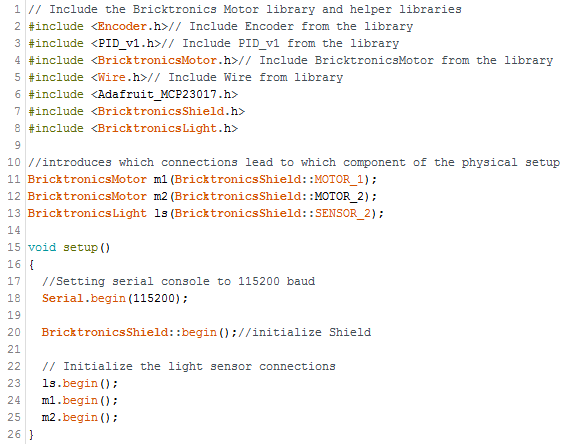
Sketch: 


Video:

  Daniela stopped 1.5 in short of the finish line. We attribute this to the lack of friction as we read the values next to the computer and its presence on the 5 ft course.

2) Touch Switch
      a) Measurement 
Sketch: We used the one from the course page
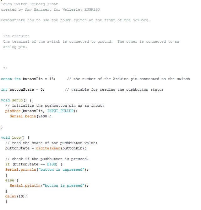
Button Readout with Narration:

      b) Stopping after 5 ft
Sketch: 


Video:

The switch worked well in stopping the SciBorg without moving too far or too short. We put a solid in front of the car to touch switch. In retrospect, I think this object was also strong enough to stop the low-torque car without the switch control. With more time, I would investigate how hard one has to press the switch for the SciBorg to stop. On the other hand, this method eliminates chances that the SciBorg stops too short because the switch is only pressed at the finish line. 

3) Light Sensor
      a) Measurement
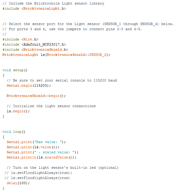
Sketch:
Videos of Readout:
        First we tried the readings with the LED on. To do so, we got rid of the comment signs before the last three lines before delay(). This allowed us to see where the LED, therefore, the sensor is pointing. We also used it to identify what height gives a sharper area. However, the differences between different colors were not apparent because LED light reflected off of surfaces more than the light in the room.

Then, we read the values without LED (commenting out the lines commanding the use of LED). This gave a better reading with distinct values for different colors. We placed the table surface (light brown), a black paper, and a white paper under at different points to obtain the following readout. 


      b) Stopping after 5 ft
Sketch:


Video:

The light sensor worked very well; the SciBorg stopped with an uncertainty of less than half an inch from the finish line. We placed a white paper at the finish line  and ordered the SciBorg's motors to stop the moment the value read by the light sensor exceeded 90, which is true for the white paper. Since light travels at the maximum speed of any known being, the reaction time was almost solely due to the processing time. Also, since the white paper only started from the finish line, there was no chance of the SciBorg stopping before the finish line.

4) Ultrasonic Sensor
      a) Measurement 
Sketch from course page: 

Video of Readout:


      b) Stopping after 5 ft
Sketch:

Video

We put a delrin sheet 20 inches from the finish line (because the ultrasonic reads distances greater than 20 inches better) and programmed the SciBorg to stop at a value we measured from the readings to correspond to what is physically 20 inches away. It worked pretty well with an uncertainty of less than an inch. Although we should note that the readings from Arduino aren't unique to a length, so the approximation we make can affect the functionality significantly. 

Bang-Bang Control to Drive Straight (Using Encoder) 

 We tried to move our SciBorg in a straight line on the lab floor with some success, and on the ramp outside with little success. Below, I present the lab floor trial. With more time, I will investigate how the SciBorg acts on a ramp and a carpet.

Sketch:

Video showing Daniela following a relatively more straight line:


On the lab floor


On the carpet outside: We placed the car on the white line to have a reference.


On a the ramp:
On the ramp, our SciBorg tilted to the same side of the ramp both when going upwards and downwards. This may indicate a tilt in the ramp itself rather than a significant problem because if it had been due to an uneven speed in the motors, the car would have consistently fallen off either to the right or left of itself and not to the same side of the ramp.


We picked the encoder for this task because it needs no external signals. In contrast, a light sensor would need some line to follow, an ultrasonic detector needs some obstacles in front of it, and a switch needs to be pressed by an external body. We designed this for the case when the SciBorg goes straight based on the rotation of its wheels (motors) rather than its interactions with external objects designed for the specific purpose. 

We learned that the Encoder, while relatively independent of external guidance, is very imprecise due to the inconsistency in the friction the wheels feel, battery power over time, etc.


Bang-Bang Control to Follow a Marked Path (Using Light Sensor)

Sketch:
We tried several sketches like the one displayed below with loops including if/else clauses that make the SciBorg turn to the left or to the right depending on the light sensor reading. However, there was no way of telling if the sensor is reading a low value because it has strayed to the left or to the right. Plus, going straight ahead often made the SciBorg overshoot the line and stray off forever. This made the motion of the SciBorg unpredictable and we had to change it to a while loop and adjust the physical placement (relative to the line to follow) of the sensor itself. 
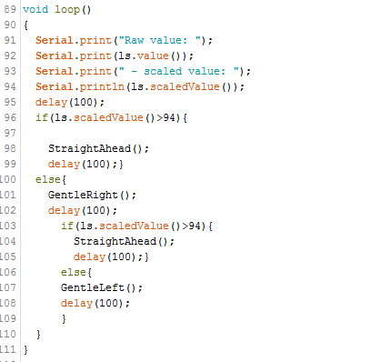
Failed attempt at using if/else commands to make the SciBorg follow the white line 
In our final iteration, we adjusted the sensor to sit right above (or a little to the right) of the right-hand-side edge of the white line to follow. Watch the video below for a visual. We used the "While" loop as shown in the sketch below to tell the SciBorg to either turn right (where a brown background lies) when it detects white (value > 80) or turn left (where a white tape lies) when it detects brown (value < 80). We avoided the "StraightAhead" function completely because the difference in the motors doesn't allow the SciBorg to go perfectly straight ahead, anyway. 


Daniela at Work

Reflections: This exercise required an outside-the-box thinking where a straight path (which in theory works well) is actually counterproductive. While the car looked "confused" turning left and right very quickly, it followed the path best when it was set to turn right or left depending on the value read by the sensor. The problems with the SciBorg made it a more realistic problem to deal with. 

The height at which we attached the light sensor to the SciBorg originally was too high and read very similar values for the brown and white surfaces. We adjusted the sensor to sit slightly lower such that the difference in values was unambiguously distinguishable.


Following an Object or other SciBorgs

On Friday, March 11th, we challenged Daniela to socialize a bit and follow other SciBorg using her ultrasonic sensor.

An ultrasonic sensor reads the distance of an object in front of it by sending a wave (of known speed) and timing how long it takes to return (distance = velocity*time).

We know our sensor reads values beyond 20 inches better. And we know the approximate reading on the Arduino program that corresponds with an object placed 20 inches away. So, we programmed our SciBorg's motor to run at approximately equal speeds correcting for its natural bend when it detects objects beyond 20 inches and to stop when it detects anything closer.

Sketch:


Video 1: Daniela Following another SciBorg


Video 2: Daniela Following Thessaly's feet


This worked pretty well as Daniela followed a Delrin sheet, another SciBorg (a new friend!), and our feet. We didn't measure how far off from the 20 inch distance the SciBorg stopped or how much later than the object in front of it. However, it did the task of stooping when the object ahead stopped and moving when the object ahead moved further. I can imagine this being useful in traffic where the distance between cars needs to be maintained at some minimum limit.


Tuesday, 8 March 2016

SciBorg Part 1

SciBorg Part 1
Goals:
* Learn how to make functions as given in the SOS code, instead of typing codes over and over.
* Get familiar with a Sci-borg and change its behavior (rather that of its two motors)

1) Making functions:
We copied the given code; made a simple circuit connecting an LED and a resistor to the Arduino hardware; and ran Morse's code.

After some confusion about whether a pin provides the voltage needed or we need to connect the LED to the 5 V output directly, we figured the pins are also power outputs.

The product of this practice was an SOS pattern with dot, dot, dot; dash, dash, dash; dot, dot, dot.

Where,
dot : a blink
dash: a longer blink taking three times as long as the dot


Next, we worked with a sci-borg:

1) We set up the Arduino board and the shield on top of the car as shown below:

sharp turn 


When connecting the shield to the Arduino board, we aligned the shield's pins to the corresponding holes in the Arduino board and pushed them in carefully. Using NXT cables, we connected the motors to the motor ports on the shield. Following the instructions, this was a very straightforward process. 


2) We ran one of the motors according to the following code:
The wheel connected to the said motor (motor #1) rotated back and forth according to the loop command. 


The Arduino program displayed messages like:


The display was reading gibberish at first because we forgot to set the bits per second to 115200 baud to match the code. Once we adjusted the bits per second, the reading matched the behavior of the wheels. 

3) We ran both motors at once after adjusting the code as displayed below:

Since there are only two motors, we copied the code instead of creating a function. With a more repetitive code, a function would be more efficient. 


4) We adjusted the code and played with the speed until we could find the slowest speed at which the sci-borg can travel:

We used the following code:


Notice we didn't use a delay () command so that the car would run nonstop. 

On a table surface, it moved without stuttering starting at 85 mm/s. The friction on the floor was too high for it to move without stopping at this same speed.

The result is shown in the following video:


5) We modified the sketch further to make the car take a hard turn. 
This almost looked like the car was pivoting on one wheel. 


We adjusted one wheel to be much faster than the other, to accomplish this. This makes the car turn to the side with lower speed. 

While this was a pretty sharp turn, it wasn't the absolute extreme. So we set the wheels at the maximum speed but in opposite directions as shown in the following and got the car to make a hard turn (the maximum it can).


6) We modified the relative speeds of the motors (made the difference smaller) so that the car can take a gentler turn. 


7) We timed the sci-borg as it covered 9 ft on the surface of two tables and adjusted its run time so it stops at exactly the time it took to travel 9 ft. 
This was the most challenging task of this lesson because regardless of our efforts to adjust the relative speeds of the wheels to keep the car moving straight, it kept going on a bent path in a very unpredictable manner. So the time measured as well as the distance traveled at any given setting of motor speeds had some uncertainty. 

Based on physics, a = (vf - vi)/ t , where a = acceleration; vf = final velocity; vi = initial velocity, and t = time elapsed between final and initial velocity (during acceleration). So the car cannot come to stop immediately at the finish mark because it would have some reaction time. Other wise, if t = 0, acceleration = infinity. Using this logic, we expected the sci-borg to pass the finish line and stop. 

However, since the measured time and length were both significantly affected by the unexpected turns, the car stopped about 15 cm before its finish line. We were looking at the back wheels to mark the beginning and end of the journey. So when the back wheels were at the start line, t = 0, displacement =0, and when the back wheels pass the finish line, the car is considered to travel 9 ft. 

Here is a video that shows our sci-borg travel 9 ft with some difficulty in keeping a straight path, but more smoothly so than it did on the floor. 


To get this result, we used the following code:


Notice motor 1 is faster than 2 because we wanted to correct for an initial condition when the car was turning slightly towards wheel #1 when the motors were set to travel at the same speed.


And, of course, by now we were attached to our sci-borg and named him Daniel! 


Thank you for your time.

Meba


Friday, 4 March 2016

Arduino Part 2


Outline of process
In the second part of our introduction to Arduino, we learned and accomplished the following:
1) We used a photocell to measure brightness of light shining on it, and to change the blinking rate of LED lights;
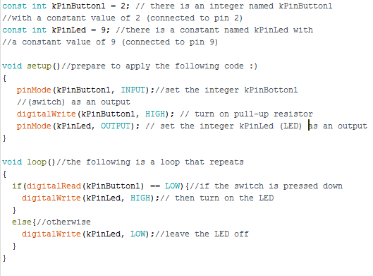
2) We used a tactile switch connected to the Arduino to turn an LED on and off
3) We used the "sweep" code from the Arduino library to make the Servo rotate between 0 and 180 degrees.
4) We used the "knob" code from the Arduino library to make the Servo follow the rotation of a potentiometer from 0 to 180 degrees and then from 0 to 60 degrees.

1)  Using a photocell measure brightness 


Notes:
We used the 1 k Ohm resistor because it worked best with the given values quantifying brightness. The resistor helps control the voltage across the photocell and prevents short circuits. We also grounded the resistor which is connected to the entire circuit in series. The coding was straightforward. We used our hands to cover the photocell to different degrees and judge the label of the brightness to the best of our ability. We also used flashlights to see readings of "bright" and "very bright". We noticed a 1 digit boundary between the different labels of brightness is really impossible. The boundaries are all approximations and not objective truth. 


2) Using a photocell to control LED behavior


Notes: Here, we used the delay function in combination with the analogue input of the photocell to vary the rate of blinks of an LED. We set an input of a value of brightness from the photocell to translate into a certain rate of blinking output in the LED. This is shown in both the code and the video above. 
The most challenging part in setting this up was figuring out what about the LED to vary. Since we already had some experience with blink, we incorporated the delay function to give this pattern controlled by the photocell.

3) Using switch to control LED behavior
Note: This was a straight forward process in which we followed the circuit diagram and the code provided to use a button to turn on an LED (when button is pushed). Although this was a basic process that can be accomplished by a simple circuit, I believe it is just an introduction to more complex systems where the use of Arduino would actually be more efficient. 

4) Using "sweep" code to control Servo

Note: We used the above code and arduino.cc's explanation on the function of the different pins on a Servo to figure out what connections to make while making the circuit. Since the code defined 9 as pin attached to the Servo, we connected it to the middle (orange) tip of the Servo. We also connected the red tip to the 5V power supply and the black tip to the ground. 
Once the program was run, the servo started rotating from 0 to 180 degree continuously as expected. 


5) Using "knob" code and a potentiometer to control Servo


We modified the circuit in #4 above by adding a potentiometer to the circuit. We connected the middle pin of the potentiometer to the 5 V outlet, the pin at one end to pin A0, the analog output suggested in the code above, and the other pin on the potentiometer to the ground. We also kept the connection between the 5 V outlet and the Servo.

This allowed us to control the rotation of the Servo with the turn of the potentiometer. I found it interesting that the potetiometer and the servo rotated at the same speed. 


Code and Video for rotation between 0 and 180 degrees


Code and video for rotation between 60 and 180 degrees


With more time, I would be interested in finding out how to manipulate the speed of rotation of the Servo using the Arduino code and/or the potentiometer.

Tuesday, 1 March 2016

Arduino Part 1

Friday February 25th, 2016
We learned how to make circuits out of an Arduino micro controller, LEDs, resistors and a potentiometer using a breadboard.  We used these connections and Arduino codes to turn LED lights on and off as well as create patterns with them both with a delay function on the code and without it using a potentiometer.


Blink:

First, we used the "Blink Practice" code from the example codes on the program to turn on one LED connected to Pin 13 for a number of milliseconds and off for a number of milliseconds. When we got to 10 milliseconds, the LED appeared to be on continuously because it was blinking too fast for our eyes to see.

Below are some pictures of the codes we used to vary the blink rate.


Some notes that helped us in making the circuit.


Here, we used a 1 kilo Ohm resistor to control the current flow through the LED. And we used the 5 V pin for power supply. The code we wrote turned the "switch" on or off. Therefore, we used a digital system to operate the LED. 


Later, we wrote a code for three LEDs connected to pins 11, 12, and 13 and played with the delay() values to create patterns.


This code, for example gave us a pattern shown in the following video.


We learned that we can create so many more interesting patterns by just varying the delay time.

Using a potentiomenter to change LED behavior:
Then, we introduced a potentiometer to our circuit to control the amount of resistance in the system and therefore the voltage across the LEDs. The potentiomenter is an analogue system that can increase or decrease the voltage across LEDs continuously.


We used the following code to introduce the potentiometers (connected to Pin 12) to the code as an integer and control one of the LEDs with the potentiometer.


We used the next code to control all three LEDs with the potentiometer. Here, the potentiometer controls the rate of blinks while the code controls the pattern, or the order in which the LEDs blink.


In this code, we named the LEDs differently so that the pattern is the same for two of them and different for the other. Keeping this pattern the same, we can increase or decreases the potentiometer value to vary rate.

The product of this arrangement is shown in the following video.


A slightly different code, with Pin_LED defined as one rather than 3 different variables/integers gave as a simpler patter with all three LEDs going on and off at the same time.